
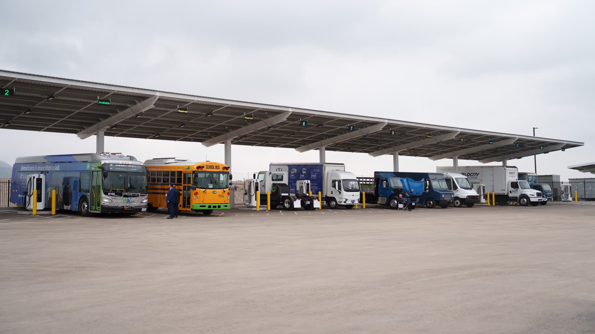
Commercial fleets and construction projects sometimes need electric vehicle charging before permanent utility service is available. The site may be temporary, the grid connection may be delayed, or the existing electrical service may not have enough spare capacity for the required chargers.
Mobile battery storage can supply Level 2 charging for a defined operating window, buffer a limited grid connection, or work with a generator and solar array. It cannot create unlimited energy. The daily vehicle requirement, charging schedule, charger output, conversion losses, and battery recharge plan must all be established.
This guide explains how to size a temporary battery-supported charging system for work vans, pickups, light equipment, support vehicles, and small commercial fleets.
Begin with energy required by the vehicles
Charger power in kW describes the charging rate. Vehicle energy in kWh describes how much electricity must be delivered. These are separate requirements.
For each vehicle, collect:
- Usable vehicle battery capacity
- State of charge on arrival
- Required state of charge at departure
- Daily driving or equipment operating hours
- Vehicle AC charging limit
- DC charging capability where applicable
- Arrival and departure times
- Minimum charging time available
- Seasonal changes in route energy use
- Auxiliary loads such as cab heating, refrigeration, tools, or export power
The energy requested by one vehicle can be estimated as:
Vehicle battery capacity x change in state of charge = energy delivered to the vehicle
An 80 kWh vehicle arriving at 30% and leaving at 80% needs approximately:
80 kWh x (0.80 - 0.30) = 40 kWh
Charging losses mean the stationary battery must provide more than 40 kWh. If the complete charging path is assumed to be 90% efficient for planning:
40 kWh / 0.90 = 44.4 kWh drawn from the stationary battery
Use measured charger input and vehicle energy where available. Efficiency changes with charger type, power level, temperature, battery state of charge, cable losses, and auxiliary loads.
Add the daily fleet demand
Prepare a schedule for every vehicle rather than multiplying one vehicle by the fleet size. Some vehicles may need only a top-up, while others may return nearly depleted.
Worked example: two commercial vans
Assume two vans each require 30 kWh delivered before the next shift:
| Vehicle | Energy delivered to vehicle | Planning efficiency | Battery energy required |
|---|---|---|---|
| Van 1 | 30.0 kWh | 90% | 33.3 kWh |
| Van 2 | 30.0 kWh | 90% | 33.3 kWh |
| Total | 60.0 kWh | 66.7 kWh |
Adding a 15% operating reserve for schedule variation and battery reserve gives:
66.7 kWh x 1.15 = 76.7 kWh
The reserve percentage is not a universal standard. Increase it where routes vary, charging is critical to the next shift, temperatures are low, or backup charging is difficult to arrange.
Check charger power in kW
The U.S. Department of Energy's Alternative Fuels Data Center notes that charging time depends on vehicle battery condition, battery capacity, charger type, charger output, and electrical-service specifications. It also reports that many Level 2 chargers operate at 7.2 kW.
Two 7.2 kW chargers operating simultaneously create a 14.4 kW load before auxiliary equipment and losses. If both run for five hours, their maximum delivered energy is:
14.4 kW x 5 hours = 72 kWh
The actual vehicle energy may be lower because a vehicle can reduce its charging rate as the battery fills, and because charger and vehicle limits can prevent operation at nameplate output.
For the stationary battery and inverter, verify:
- Charger input voltage and phase
- Continuous input current
- Maximum simultaneous charger load
- Charger power factor and harmonics
- Startup and control-power requirements
- Cable length and voltage drop
- Other loads on the temporary distribution system
- Battery inverter continuous and overload ratings
Three 11.5 kW Level 2 chargers would request 34.5 kW if all operated at full output. A 30 kW source could not supply that load without charge management or a lower setting.
AC Level 2 and DC charging are different systems
Level 2 equipment supplies AC power to the vehicle's onboard charger. The vehicle determines how much AC power it can accept. Installing a higher-rated EVSE does not make a vehicle charge faster than its onboard limit.
DC fast charging converts AC to regulated DC outside the vehicle and communicates directly with the vehicle battery system. It generally requires more input power and specialized equipment. A commercial battery system with AC output does not become a DC fast charger simply because its inverter has enough kW.
For temporary DC charging, confirm the charger input, vehicle connector, communication protocol, grounding, isolation, fault protection, environmental rating, and compatibility with the battery source. Use equipment intended and certified for that service.
The Skyridge Power product comparison in this article focuses primarily on supplying compatible AC charging equipment. Any DC charging arrangement requires a separate engineering and equipment review.
Use charging schedules to stay within the power limit
Not every vehicle needs to charge at the same time. Managed charging can sequence or reduce charger output so the combined load remains within the temporary source rating.
For example, four 7.2 kW ports have a connected rating of 28.8 kW. If each van requires only 18 kWh overnight, the fleet needs 72 kWh delivered. The system can rotate charging between ports rather than operate all four at full output for the entire period.
Useful controls include:
- Site-wide maximum power limit
- Per-port current limits
- Scheduled start and stop times
- Priority by departure time
- Minimum required state of charge
- Dynamic response to other site loads
- Low stationary-battery state-of-charge limit
- Generator or grid recharge coordination
The charging plan should retain enough time to recover from a late arrival, charger fault, or missed connection.
Battery buffering for a limited grid connection
A site may have grid power but not enough capacity for the desired charging peak. A battery can charge slowly from the available service, then combine stored energy with the service during the fleet charging window.
Suppose a site has 5 kW of spare grid capacity available for 16 hours outside the charging period:
5 kW x 16 hours = 80 kWh before charging losses
That energy can refill part of a battery before the vehicles return. During charging, controls must prevent the combined site load, battery charger, and EV chargers from exceeding the service limit.
Battery buffering does not remove utility, electrical-code, or interconnection requirements. The service, transfer equipment, charger controls, and battery connection must be designed and approved for the intended operating mode.
Plan the battery recharge source
A temporary EV charging system needs a repeatable way to restore the stationary battery. Options include:
Grid charging
Grid charging is usually the simplest where a limited service is available. Record the maximum permitted charger power and the time available between vehicle charging sessions.
Generator charging
A generator can recharge the battery during a scheduled period instead of running continuously at low load. It must be sized for charger demand plus any concurrent site loads. Controls need clear start, stop, reserve, and fault logic.
Our comparison of battery electric and diesel generators for commercial sites explains the operational differences.
Solar charging
Solar can offset some daily vehicle energy, particularly during long daytime parking periods. Production depends on array size, location, season, cloud, smoke, snow, shading, orientation, and charge-controller limits.
An EV fleet can consume tens or hundreds of kWh per day, so panel area and seasonal production should be modelled before solar is treated as the primary recharge source. Our guide to solar charging in cloudy weather covers the main variables.
Battery rotation
A rental or project fleet may rotate charged battery units between a depot and the worksite. Transport, lifting, connection time, state-of-charge verification, and backup inventory then become part of the operating plan.
Include other temporary site loads
EV charging may share a battery system with office trailers, lighting, tool charging, security cameras, or pumps. These loads reduce the energy and power available to vehicles.
Prepare one combined interval schedule. A 14.4 kW EV charging load plus a 6 kW office and lighting load creates 20.4 kW of simultaneous demand. If an electric heater starts during that period, the total can increase quickly.
Internal links to our site office trailer sizing guide and portable power for jobsite tools provide examples of these supporting loads.
Where vehicle charging is operationally critical, consider reserving battery energy for the fleet rather than allowing unrelated loads to discharge the system below the next-shift requirement.
Cold weather changes both sides of the calculation
Low temperature can increase vehicle energy use for cabin and battery heating while also affecting the stationary battery and charging system. Charging power may be reduced until the vehicle battery reaches an acceptable temperature.
Winter planning should cover:
- Higher route energy use
- Vehicle battery preconditioning
- Reduced charging rate at low state of charge or low temperature
- Stationary battery charge and discharge limits
- Cable flexibility and connector condition
- Snow clearing around chargers and solar panels
- Enclosure heating and its energy use
- Additional schedule reserve
Use measured winter fleet data where possible. Our cold-weather battery power guide covers stationary-battery temperature planning in more detail.
Temporary installation and safety review
EV charging is a continuous electrical load and must use suitable equipment, overcurrent protection, grounding, bonding, disconnects, cable management, and ground-fault protection. Chargers and connectors need environmental ratings appropriate for rain, snow, dust, mud, and vehicle traffic.
Site planning should address:
- Protection from impact by vehicles and equipment
- Stable charger and battery placement
- Cable routes that avoid trip and crushing hazards
- Emergency shutdown and disconnect access
- Fire-department and service access
- Lighting and signage around charging bays
- Inspection of connectors and cables
- Network access for charger controls and reporting
- Permits and inspection by the authority having jurisdiction
Canadian requirements vary by province, and U.S. requirements vary by state and local authority. A qualified electrical contractor should design and verify the temporary installation.
Commercial mobile charging approaches
Battery-supported mobile charging is already offered for temporary and fleet applications. Allye markets mobile battery systems with integrated or separate charging for construction, events, film, and mobile fleets. GCK Energy combines mobile storage with a 40 kW DC charger for construction sites. Atlas Copco offers a towable rapid charging station for off-grid and temporary installations.
These systems cover a broad range of power and capacity. Their specifications should not be applied directly to another project. The correct system depends on vehicle energy demand, charger type, charging window, site electrical configuration, recharge source, transport limits, and local approvals.
Where Skyridge Power systems fit
The Apex Station is the closer match for the two-van worked example. Its published specifications include:
- 120 kWh of LiFePO4 storage
- 30 kW continuous output
- Configurable 120/240 V output
- Single-phase and three-phase configurations
- Grid, generator, and solar charging compatibility
- Up to 30 kW of solar input
The example's 76.7 kWh planning requirement is below the Apex Station's published 120 kWh capacity. Two 7.2 kW chargers create a 14.4 kW load, which is below its published 30 kW continuous output. Final compatibility still depends on EVSE voltage and phase, protection requirements, usable reserve, conversion losses, temperature, other site loads, and the recharge schedule.
The Apex Mobile provides 16 kWh nominal capacity, 14.4 kWh usable capacity, and 12 kW continuous output. It may support one compatible Level 2 charger for a limited top-up. At 90% charging-path efficiency, 14.4 kWh from the battery would deliver approximately 13.0 kWh to a vehicle before retaining any additional operating reserve. It is not sized for the full two-van example.
Neither product should be described as an EV charger on its own. A compatible, approved EVSE or DC charger, temporary distribution system, and project-specific electrical design are still required.
Skyridge Power can review vehicle energy records, arrival and departure schedules, EVSE specifications, site service capacity, other temporary loads, and available recharge sources to prepare a battery-supported charging configuration.
Planning checklist
- Calculate the kWh required by each vehicle between arrival and departure.
- Include charging-path losses and an operating reserve.
- Confirm each vehicle's maximum AC or DC charging rate.
- Record charger input voltage, phase, current, and connector type.
- Add simultaneous charger power and all other site loads.
- Use managed charging where connected load exceeds source capacity.
- Define the grid, generator, solar, or rotation-based recharge plan.
- Model winter route energy and charging behaviour.
- Keep vehicle charging energy separate from non-critical site loads where needed.
- Confirm temporary distribution, protection, grounding, permits, and inspection.
- Test the complete charging sequence before relying on it for the next shift.
- Monitor stationary battery state of charge, charger status, and vehicle completion.
Primary references include the U.S. Department of Energy Alternative Fuels Data Center overview of EV charging stations and its best-practices guide for EVSE installations. Commercial examples include Allye mobile battery-supported charging, GCK Energy construction-site charging, and the Atlas Copco mobile rapid charging station.
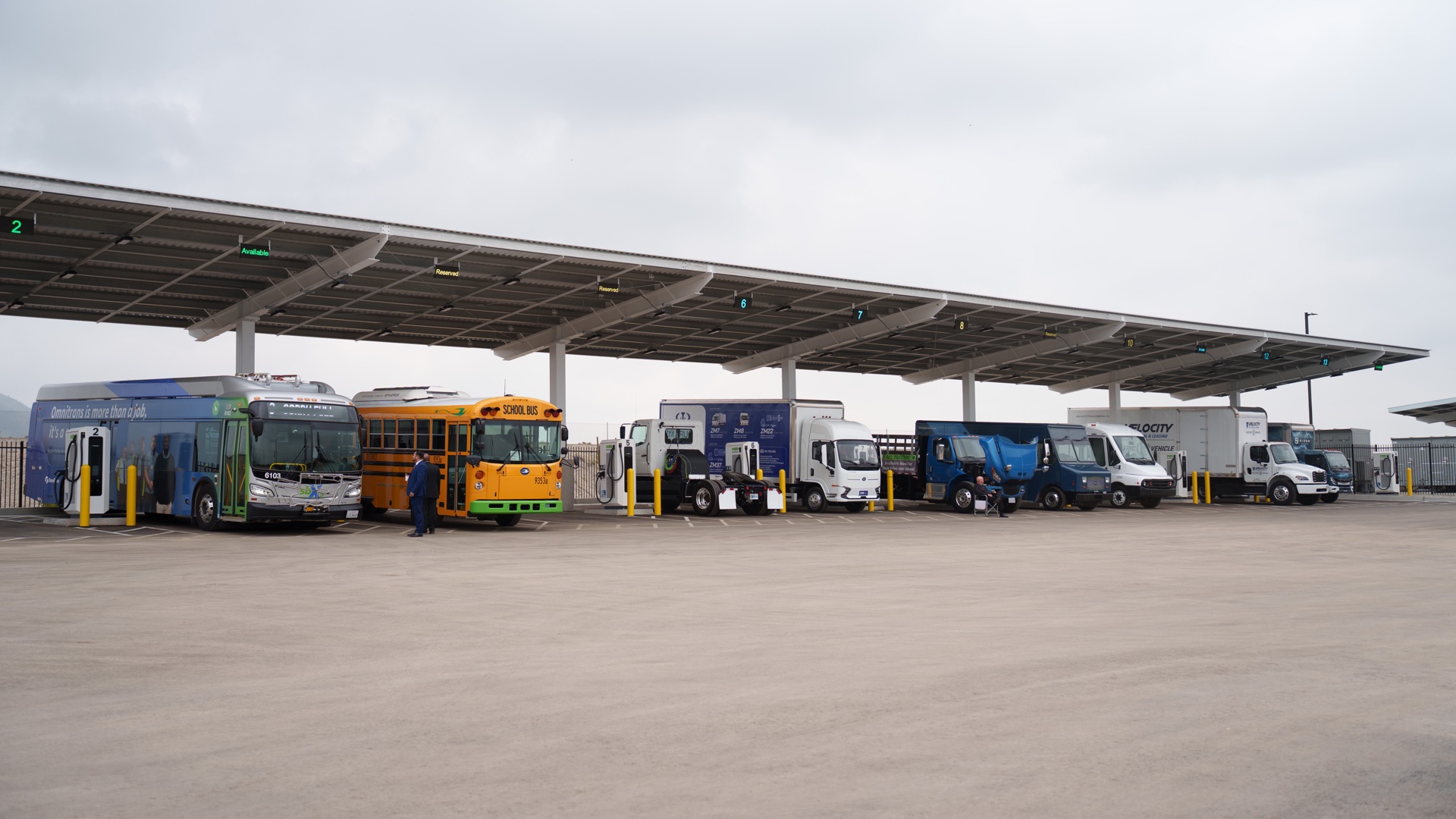
Image source: Trucks charging at Greenlane.jpg by Zenroute, licensed under CC BY-SA 4.0. The image was cropped and resized to a 1920 x 1080 landscape format.
