
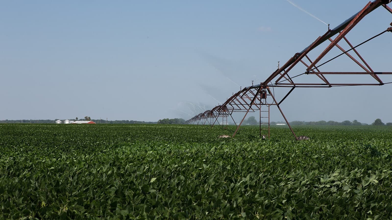
Farm irrigation systems often place a concentrated electrical load far from the nearest useful service connection. A pump may operate for several continuous hours, while its motor can draw a much larger current for a short period during startup.
Mobile battery storage can support selected irrigation pumps, booster pumps, fertigation controls, valves, sensors, and communications equipment. It can also work with solar or a generator where the daily pumping schedule exceeds the energy stored in the battery.
The equipment cannot be selected from motor horsepower alone. A complete plan needs the pump's measured or documented running power, starting method, voltage, phase, operating hours, required water delivery, site conditions, and recharge plan.
This guide explains how to prepare that information and how to compare it with a commercial mobile battery system.
Begin with the irrigation requirement
Electrical sizing should follow the required water flow and pressure. The pump needs to deliver the intended flow against total dynamic head, which includes elevation, operating pressure, and friction losses through pipes, valves, filters, and irrigation equipment.
The B.C. Sprinkler Irrigation Manual covers water requirements, application rates, set times, irrigation intervals, piping, pump selection, and power-unit selection. Oklahoma State University Extension similarly recommends evaluating the pump from flow, total dynamic head, and measured power input.
Before reviewing a battery system, document:
- Required flow rate
- Pumping water level or suction condition
- Elevation change from the source to the distribution point
- Required pressure at sprinklers, drip lines, pivots, or other outlets
- Pipe length, diameter, fittings, filters, and valves
- Daily and seasonal pumping hours
- Motor horsepower, efficiency, voltage, phase, and full-load current
- Starting method and starting-current data
- Existing variable-frequency drive, soft starter, or control panel
- Available grid, solar, and generator charging sources
If the existing pump is oversized, worn, or operating far from its efficient point, supplying it from a battery does not correct the hydraulic problem. A pump test can identify actual flow, head, electrical input, and overall pumping efficiency before a power system is purchased.
Use measured running kW when possible
A motor nameplate gives useful limits, but the actual electrical input depends on motor load, efficiency, power factor, voltage, and operating conditions.
For a single-phase load, estimated real power is:
kW = volts x amps x power factor / 1,000
For a balanced three-phase load:
kW = 1.732 x volts x amps x power factor / 1,000
These calculations are estimates when current and power factor are not measured under representative pumping conditions. A qualified technician using a power meter can provide a better running-kW figure.
Motor horsepower is mechanical output, not electrical input. One horsepower equals approximately 0.746 kW of mechanical power. A 10 hp motor therefore provides approximately 7.46 kW at its shaft when fully loaded, but it must draw more electrical power because the motor is not 100% efficient.
USDA guidance notes that electric motor efficiency and pump performance vary with size and loading. The motor and pump should be matched to the application rather than sized from a broad rule of thumb.
Calculate energy from pumping time
Once running power is known, calculate stored-energy demand:
Running power in kW x pumping time in hours = energy in kWh
For example, an irrigation pump drawing a measured 8.5 kW for six hours uses:
8.5 kW x 6 hours = 51.0 kWh
Add the power used by controls, communications, filters, valves, injection equipment, and any booster pumps. A 0.2 kW control and communications package operating for the same six hours adds:
0.2 kW x 6 hours = 1.2 kWh
The operating total is 52.2 kWh before reserve and conversion losses.
Worked example: one six-hour irrigation set
The following example is a planning exercise for one electric pump and its controls. It does not represent every irrigation system.
| Load | Planning power | Runtime | Energy use |
|---|---|---|---|
| Irrigation pump | 8.5 kW measured | 6 hours | 51.0 kWh |
| Pump controls and monitoring | 0.2 kW | 6 hours | 1.2 kWh |
| Valve and fertigation controls | 0.1 kW average | 3 hours | 0.3 kWh |
| Field communications | 0.05 kW | 8 hours | 0.4 kWh |
| Calculated total | 52.9 kWh |
Adding a 20% planning allowance for conversion losses, load variation, and operating reserve gives:
52.9 kWh x 1.20 = 63.5 kWh
If the pump runs for 12 hours instead of six, the pump alone uses 102 kWh. With controls and the same 20% allowance, the requirement moves beyond 120 kWh. That longer schedule would need more storage, a recharge period, reduced pumping time, or hybrid support.
The reserve percentage is not a fixed standard. Temperature, battery reserve settings, uncertainty in the load data, recharge access, and the operational consequence of stopping early all affect the appropriate allowance.
Check motor starting demand separately
The 8.5 kW running load does not describe the short-duration demand when the motor starts. Across-the-line induction motors can draw several times their normal running current until they reach operating speed. The exact current and acceleration time depend on the motor, pump, supply voltage, water system, and starting method.
Collect the following information:
- Full-load amps
- Locked-rotor amps or starting-current code
- Starting duration
- Across-the-line, reduced-voltage, soft-start, or VFD control
- Whether the pump starts against pressure or an open discharge
- Other loads that remain connected during startup
- Minimum acceptable voltage during acceleration
A battery inverter can have enough continuous output for the running pump and still be unable to start it. The inverter's documented surge capability, overload duration, voltage response, and compatibility with the motor controller must be checked together.
Long cable runs can add voltage drop and make starting more difficult. Cable size, connector ratings, overcurrent protection, and distribution equipment should be reviewed for the actual distance and installation method.
VFDs and soft starters
A variable-frequency drive can ramp motor speed and reduce the electrical and mechanical stress associated with direct starting. It can also adjust flow where the irrigation design permits variable-speed operation.
A soft starter reduces starting current and torque by controlling voltage during acceleration, then normally bypasses itself once the motor is running. A VFD and a soft starter are not interchangeable, and neither should be added without checking the pump curve, motor insulation, controller compatibility, harmonics, cooling, and protective settings.
When an existing pump already uses a VFD, provide the drive manufacturer, model, input current, output rating, control settings, and any line reactor or filter information to the battery-system supplier. The battery inverter and motor drive both use power electronics, so compatibility should be confirmed and tested under load.
Voltage and phase determine the connection
Farm pumps may use 120/240 V single-phase service, 120/208 V three-phase service, 277/480 V three-phase service, or another site-specific arrangement. Voltage and phase cannot be inferred reliably from horsepower.
Record the electrical data from the motor controller and supply panel, not only the motor. Confirm:
- Nominal voltage and acceptable range
- Single-phase or three-phase supply
- Delta or wye connection where applicable
- Frequency
- Grounding and bonding arrangement
- Disconnect and overcurrent requirements
- Receptacle, cam-lock, lug, or hardwired connection
- Transfer and utility-isolation method if the pump can use more than one source
Changing a pump motor, adding a drive, or using a transformer may alter the load and starting behaviour. A qualified electrical contractor should prepare and verify the temporary or permanent connection.
Consider water storage as part of the energy plan
Electrical storage is not the only scheduling option. Where the irrigation design allows it, pumping water to a reservoir or elevated tank during available solar or grid hours can separate water delivery from the electrical generation schedule.
This approach is site-specific. Storage capacity, water quality, evaporation, elevation, pump selection, irrigation pressure, land use, and permitting all need review. It can nevertheless reduce the number of hours that a battery must carry a pump at night or during a peak-rate period.
Soil moisture monitoring and irrigation scheduling can also reduce unnecessary pumping. The USDA Natural Resources Conservation Service provides an irrigation energy estimator, while provincial and university extension resources provide methods for irrigation scheduling and pump-system testing.
Battery-only, solar-assisted, and hybrid operation
Battery-only
Battery-only operation can fit a defined pumping set when the stored energy, motor-start capability, and recharge window are all established. It avoids direct exhaust and fuel handling at the pump site while discharging.
Solar-assisted
Solar can offset some daytime pumping energy or recharge the battery between sets. Available production depends on array size, season, cloud, smoke, panel orientation, temperature, and shading. Use a conservative production estimate rather than assuming the array operates at nameplate output for the full day.
Our guide to solar charging in cloudy weather explains the main production variables.
Battery and generator hybrid
A hybrid configuration can serve longer schedules. The battery can operate the pump or smaller controls for a defined period, and the generator can recharge the battery or carry the pump during extended operation.
The generator should be sized for both the connected load and charger demand. Controls need clear start, stop, low-state-of-charge, fault, and fuel-management logic. The arrangement should also retain a practical response if the generator, charger, or battery is unavailable.
Site and environmental review
Agricultural pump sites can expose power equipment to irrigation spray, dust, mud, heat, cold, rodents, chemicals, and vehicle traffic. Installation planning should cover:
- Equipment environmental ratings and operating-temperature limits
- Stable placement outside flood and standing-water areas
- Separation from irrigation spray and chemical handling
- Cable protection from machinery, livestock, and field traffic
- Ventilation and manufacturer clearances
- Grounding, bonding, disconnects, and ground-fault protection
- Fire access and emergency shutdown
- Security and unauthorized-operation controls
- Inspection before each seasonal deployment
Applicable electrical, fire, water, and environmental requirements differ across Canadian provinces, U.S. states, and local authorities. Farm operators should use qualified electrical and irrigation professionals for the final design.
Where Skyridge Power systems fit
The Apex Station is the closer fit for the six-hour worked example. Its published specifications include:
- 120 kWh of LiFePO4 storage
- 30 kW continuous output
- Configurable 120/240 V output
- Single-phase and three-phase configurations
- Grid, generator, and solar charging compatibility
- Up to 30 kW of solar input
- Less than 20 ms transfer time
The example's 63.5 kWh planning requirement is below the Apex Station's nominal 120 kWh capacity, and the 8.5 kW measured pump load is below its published 30 kW continuous output. These comparisons do not confirm that the system can start the motor. Locked-rotor current, starting method, voltage, phase, cable length, controller compatibility, temperature, reserve, and conversion losses must be reviewed.
The Apex Mobile provides 16 kWh nominal capacity, 14.4 kWh usable capacity, and 12 kW continuous output. It may fit controls, communications, a small pump with verified starting characteristics, or a short pumping period. It would not cover the complete six-hour example without recharge.
Skyridge Power can review pump nameplates, measured load data, motor-controller specifications, irrigation hours, site voltage, cable distance, and recharge sources to prepare a battery-only or hybrid configuration.
Final checklist
Before selecting a mobile power system:
- Confirm required water flow, pressure, and pumping duration.
- Test pump flow, total dynamic head, and power input where possible.
- Record motor and controller voltage, phase, full-load amps, and starting data.
- Calculate kWh from measured running kW and actual pumping hours.
- Add controls, valves, communications, fertigation, and booster loads.
- Define reserve for losses, temperature, and schedule variation.
- Verify motor starting and power-electronics compatibility.
- Check cable voltage drop and temporary distribution requirements.
- Establish grid, solar, generator, or rotation-based recharging.
- Review environmental exposure, access, protection, and local requirements.
- Test the complete system under representative hydraulic load.
Primary references include the Province of British Columbia's Sprinkler Irrigation Manual, the USDA NRCS National Engineering Handbook chapter on irrigation pumping plants, the USDA NRCS Energy Estimator for Irrigation, and Oklahoma State University Extension guidance on irrigation pump system testing.
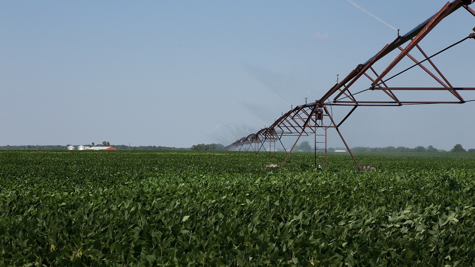
Image source: Field Irrigation by the United Soybean Board, licensed under CC BY 2.0. The image was cropped and resized to a landscape format.
.jpg)